Back to All Mod Cons
Last updated: March 26, 2011
|
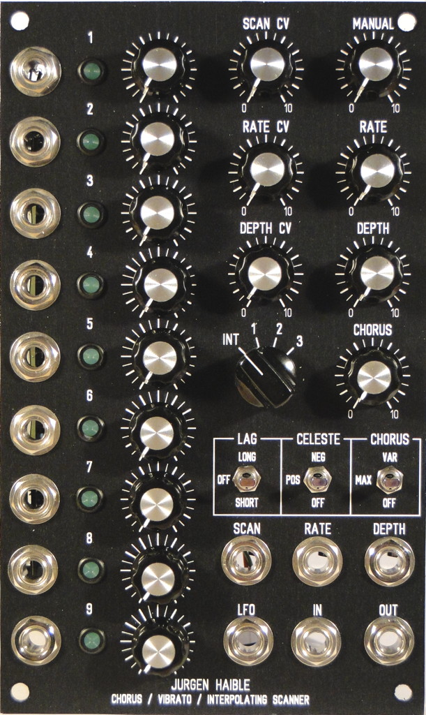
Below are details of my implementation of the JH Interpolating Scanner & Scanner Chorus/Vibrato into a 3U wide MOTM format panel. I built the super-deluxe version of this circuit that combines both the interpolating scanner and the scanner chorus/vibrato into one module. Be sure to check out Dave Brown's implementation as well because I borrowed a lot of ideas from him. I used an Electroswitch C4D0904N-A 9-pole 4-position rotary switch (Mouser #690-C4D0904N-A). This switch is quite firm so be sure to eat your Wheaties if you go with one of these. I find that it is easier to turn if I lean into a bit. You'll also need a good pointer knob; a round knob is a bit difficult to use with this switch. I wanted to use a small chicken-beak knob (Cosmo #7607 0.625" diameter, as shown in the panel mockup at left) but was unable to obtain one. In the meantime, I'm using a Davies 1510AH (Mouser #5164-1510AH). If you plan on building the super-deluxe version of this circuit, there's little point in using the three headers to attach the rotary switch to the PCB because an additional wire is needed between the PCB and rotary switch that is not available on the header. JH explains on his website which trace needs to be cut on the PCB. So save yourself the hassle and expense of using the three headers and solder the rotary switch wires directly to the PCB. Grab the schematic and follow along with the explanations below. 1. Use 5 Volt RegulatorI used a 78L05 regulator to provide a +5 volt constant voltage to the 9 interpolating scanner inputs instead of the 3K/1.5K voltage divider that JH shows on his web page. For unknown reasons, I could only get +4.5 volts maximum when I tried to use the simple voltage divider off a +/-15V supply. Fortunately, it was quite easy to place a 78L05 regulator into one of the spots reserved for a 470 uF capacitor (which isn't needed if using a +/-15V supply). I also added a 10 ohm protection resistor to the regulator output to protect the regulator from an accidental short circuit to ground when inserting plugs into the jacks. 2. More Gain For Rate CV InputI changed R94 from 470K to 220K to get more range from the Rate CV input. The default value of 470K wasn't giving me enough change in the LFO frequency with +5V signals so I lowered this to 220K. 3. Normalize Input For 10Vpp SignalsSince I'm not using a pot to limit the input level to the Scanner Chorus/Vibrato circuit, I found I was getting too much gain when using 10Vpp signals (the output was way too hot). I changed R102 from 10K to 120K and R101 from 1M to 51K to get unity gain through the scanner. 4. Remove Filter CapacitorsI'm not using the filter on the input so I left out C41 (470 pF) and C42 (1 nF). 5. Chorus SwitchI used a 3 position SPDT switch for the Chorus function (NKK M2013ES1W01-RO, Mouser #633-M201302-RO). In the lower position, R103 is shorted to ground and chorus is off (vibrato mode). In the center position, R103 (1K) sets the chorus function to maximum (full chorus mode). In the upper position, a 10K LOG pot is connected in parallel with R103 to provide a variable amount of chorus from none (0K in parallel with 1K) through maximum (10K in parallel with 1K). I found that increasing R103 above 1K didn't provide any change in the sound; it only made the output level increase from 10Vpp to 18Vpp. If you implement this mod, make sure you use a 10K LOG pot, not LINEAR, otherwise most of the useful range will be limited to the extreme counter-clockwise pot rotation. Using a log pot gives a much more useful range over the full pot rotation. R103 is soldered onto the PCB. The switch is connected to the PCB via the CH pads. 6. Celeste SwitchI used a 3 position SPDT switch for the Celeste function (NKK M2013ES1W01-RO, Mouser #633-M201302-RO). In the lower position, R104 is connected to the end of delay line providing proper termination (celeste off). In the center position, R104 is removed from the circuit. This provides reflections equal in ampitude and of the same polarity as the impinging signal (+ reflections). In the upper position, R104 is shorted. This provides reflections equal in amplitude and of opposite polarity to the impinging signal (- reflections). Positive and negative reflections can sound quite different, depending on the input signal. R104 is not soldered to the PCB, it is soldered to the two outer pins on the switch. The switch is connected to the PCB via the pads for R104. 7. Lag SwitchI used a 3 position SPDT switch for the Lag function (NKK M2013ES1W01-RO, Mouser #633-M201302-RO). In the lower position, a 10uF capacitor is connected (short lag). In the center position, no capacitor is connected (lag off). In the upper position, a 100 uF capacitor is connected (long lag). I found that a 100 uF capacitor provided lag times similar to the ramp up/down times of my own Leslie speaker. The negative ends of the capacitors are soldered to the two outer pins on the switch. The positive ends of the capacitors and the switch are connected to the PCB via the LAG pads. Insert a jumper between the two holes for C5 on the PCB. 8. Add LFO Output JackLFO Option #1 - The internal LFO can be brought out to a front panel jack simply by connecting a 1K resistor to U15B pin 7. This will provide a 20 Vpp LFO output. To bring this down to 10 Vpp, use two 2K resistors (2.2K will also work fine) in series to ground and connect the LFO output jack at the junction of the two 2K resistors. In either case, it is easiest to attach the resistors at the LFO output jack and then run a wire to R83 (100K) on the PCB rather than trying to connect directly to U15B. LFO Option #2 - Alternatively, you can use a non-inverting buffer with a gain of 1/2. This is the method I used because I had an extra op-amp on a MUUB-3 board and I prefer to have a separate output buffer for the LFO. 9. Add LED DriversIf you use the standard MOTM-style Lumex LEDs with this circuit you will be disappointed at how dim they are in use. The LEDs are driven directly by the VCA control current which tops out at about 2 mA. This is not nearly enough to drive those incredibly dim Lumex LEDs which, I find, require about 10 mA to achieve a decent level of brightness. To rectify this situation, I added LED drivers for each of the nine LEDs. One such circuit is shown in the schematic, you will need to duplicate this nine times (once for each LED). I used a couple of TL074 quad op-amps and a TL072 dual op-amp on a MUUB-3 board. Nine of the op-amps are used for the LED drivers, the tenth is used for the LFO output buffer (LFO Option #2). The MUUB-3 is mounted on top of the scanner PCB using a 1" aluminum standoff. You don't have to use a MUUB-3 board, you can use any expansion board as long as you can fit 9 op-amps on it. Install a 1K resistor (RA) on the PCB in the location where the LED would normally be placed (see the construction photos for the correct orientation of RA so that you will be able to connect up the LED driver). Run a wire from the hole where the LED cathode would have been connected (the banded end) to the op-amp on the expansion board. Add the 1N4148 diode and resistor RB on the expansion board. Run wires from the LED to the expansion board. Using a 180 ohm resistor for RB, I measured 10 mA of current through a standard MOTM-style green Lumex LED which provided a brightness identical to the other modules in my synth. Adjust RB as necessary for whatever LED you choose and however bright you want it without affecting the operation of the scanner. |
||||
Pictures
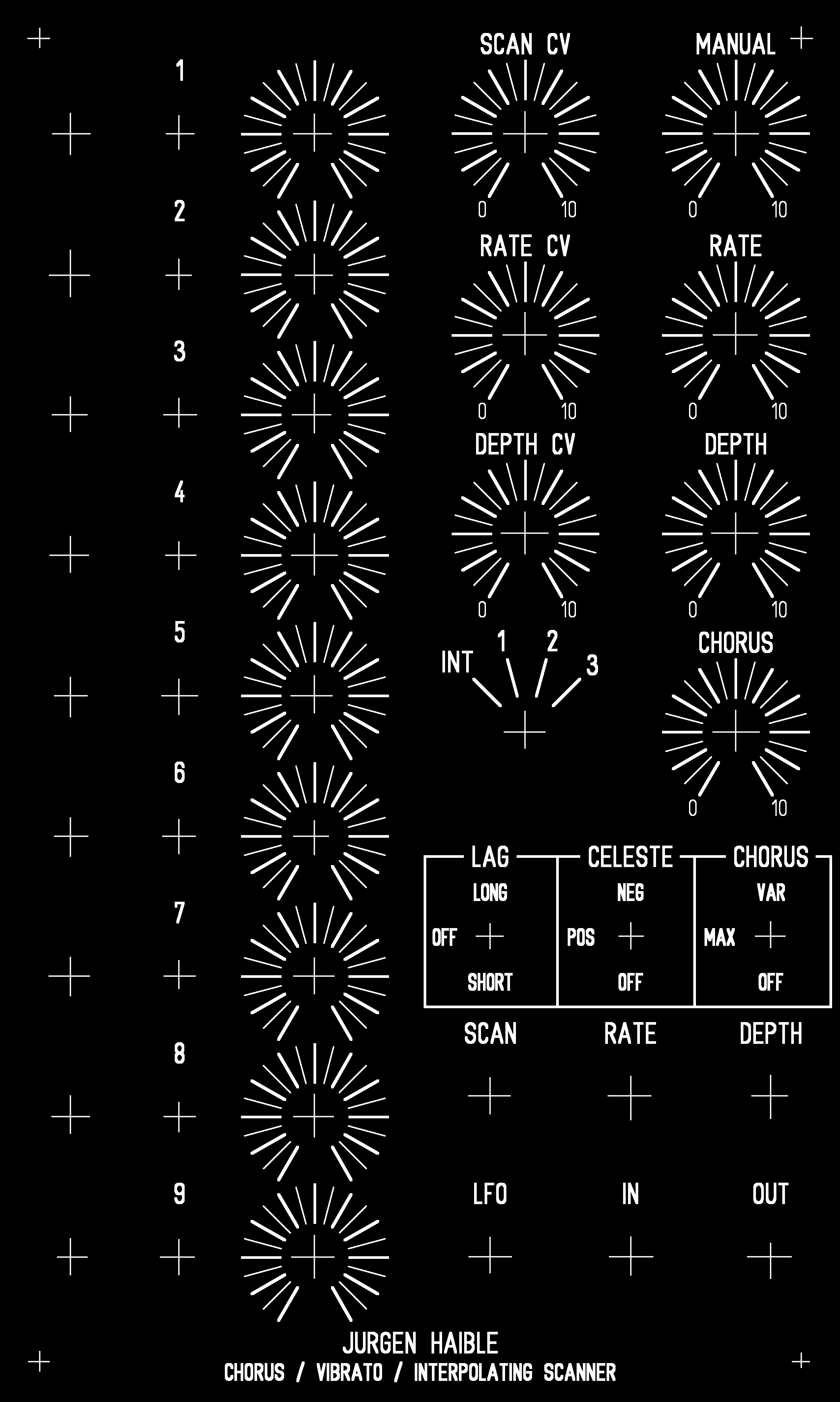
Panel LayoutI bought a sheet of 1/8" plastic (clear lexan) at a hardware store and cut that into a number of panels (1U, 2U, 3U). I made an inverted printout of the panel in Front Panel Designer (black text on white background) and used that as a guide for drilling the holes in the plastic. I then printed out a screenshot of the FPD file using a laser printer and pasted it onto one of the plastic panels. In order to get smooth diagonal lines in the printout, I had to enlarge the panel (in Front Panel Designer) by 400% and then make multiple screenshots and stitch them together in a graphics program. Finally, I used an X-Acto knife to carefully remove the paper that covered the holes. The end result is not as sturdy as a metal panel, and doesn't provide any shielding, but it looks quite good and most people can't tell it's any different from the metal panels in my synth. |