 |
 |
 |
 |
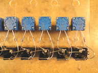
| Wiring detail for input pots and jacks. |
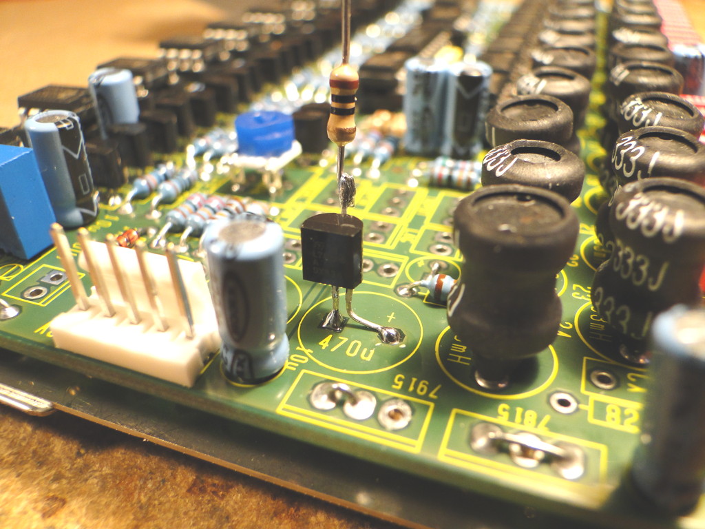
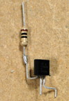
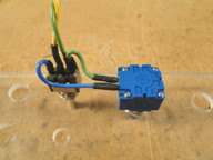
Front view of 5V regulator with 10 ohm resistor. |
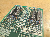
Front view of 5V regulator on PCB. |
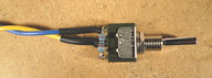
Rear view of 5V regulator on PCB. Heatshrink over 10 ohm resistor. Black wire is ground connection to front panel input jacks. |
 |
 |
 |
 |
| Chorus switch and pot detail. |
Celeste switch detail. |
Lag switch detail. |
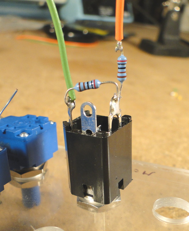
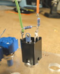
LFO option #1 jack detail (two 2K resistors to divide 20Vpp down to 10Vpp). |
 |
 |
 |
 |
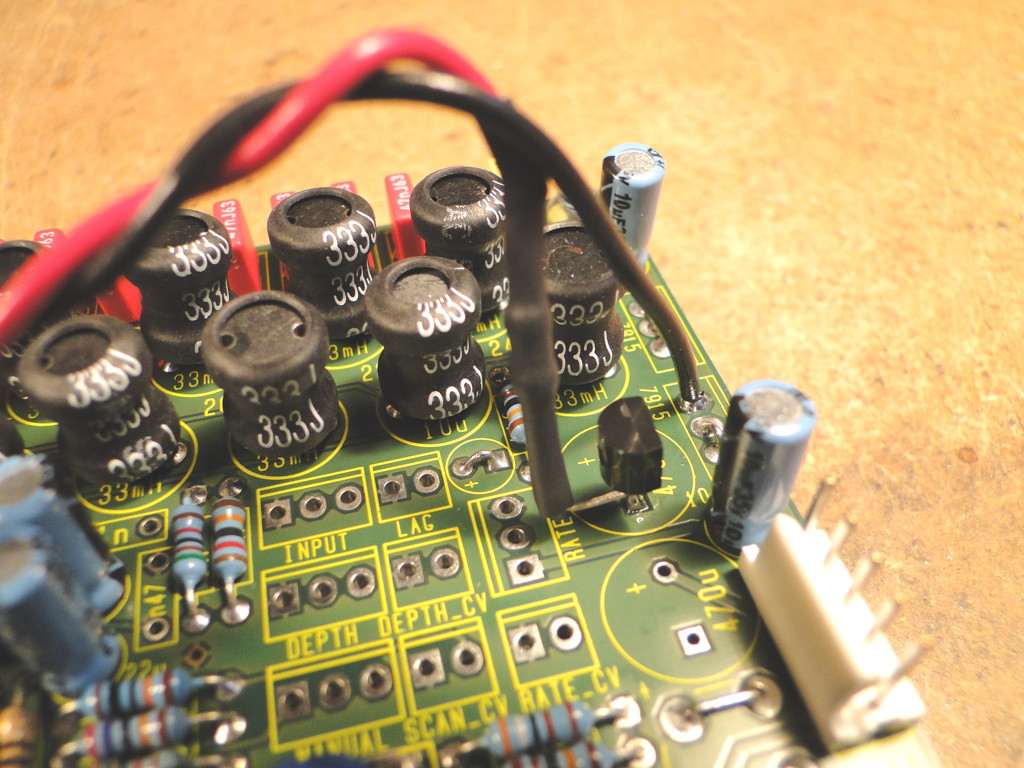
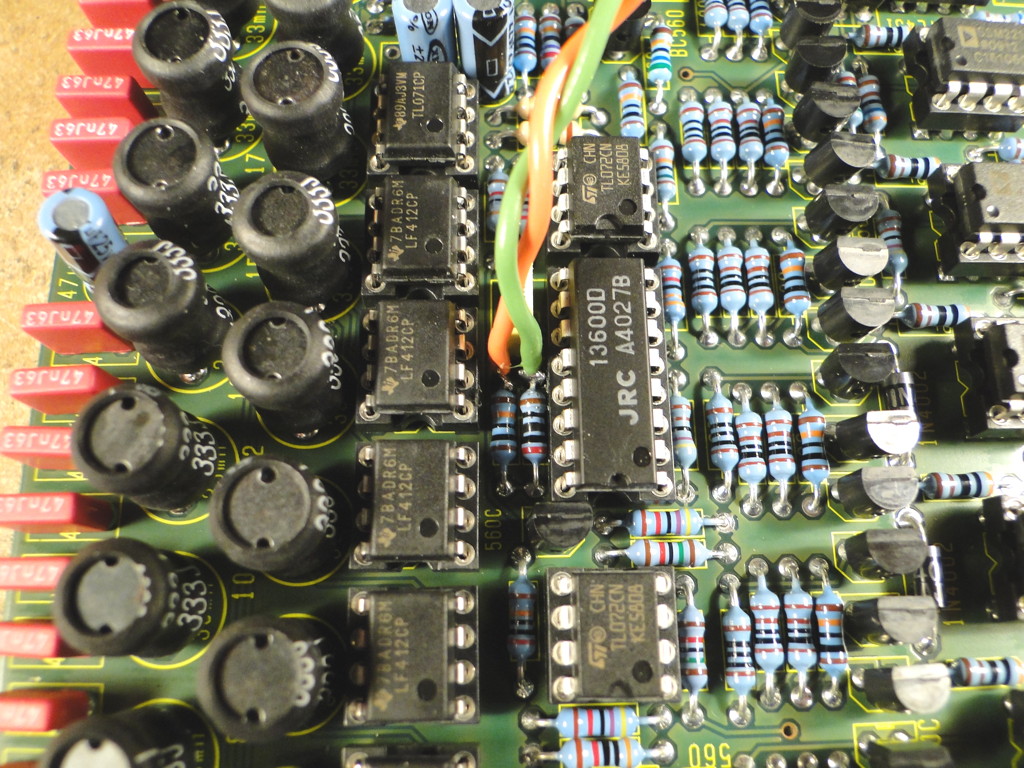
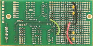
| LFO output location on PCB (R83). Orange wire is signal, green wire is ground. |
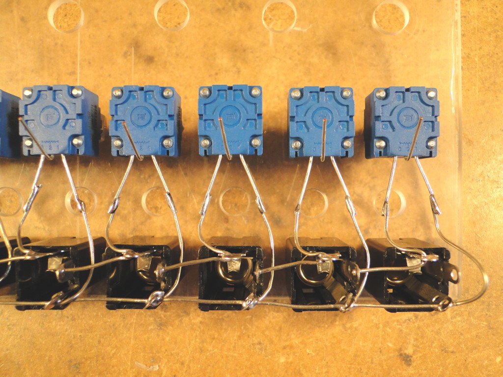
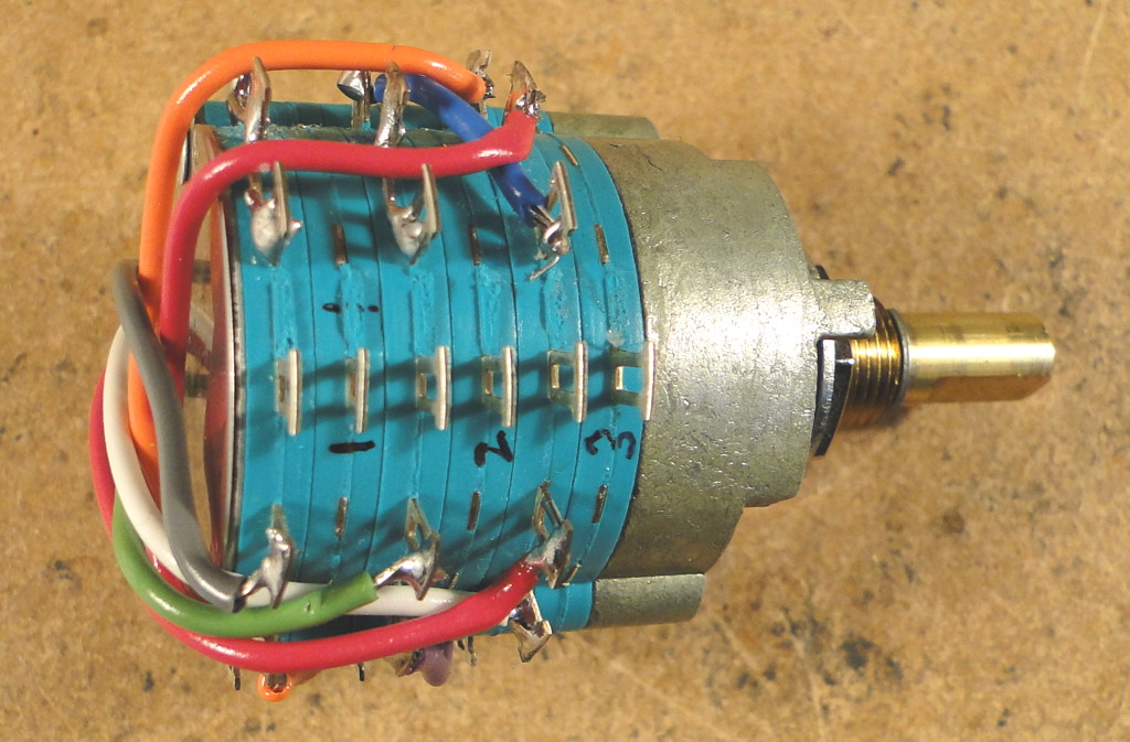
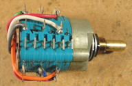
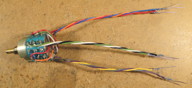
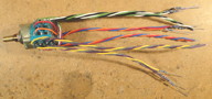
Rotary switch jumper detail (view #1). |
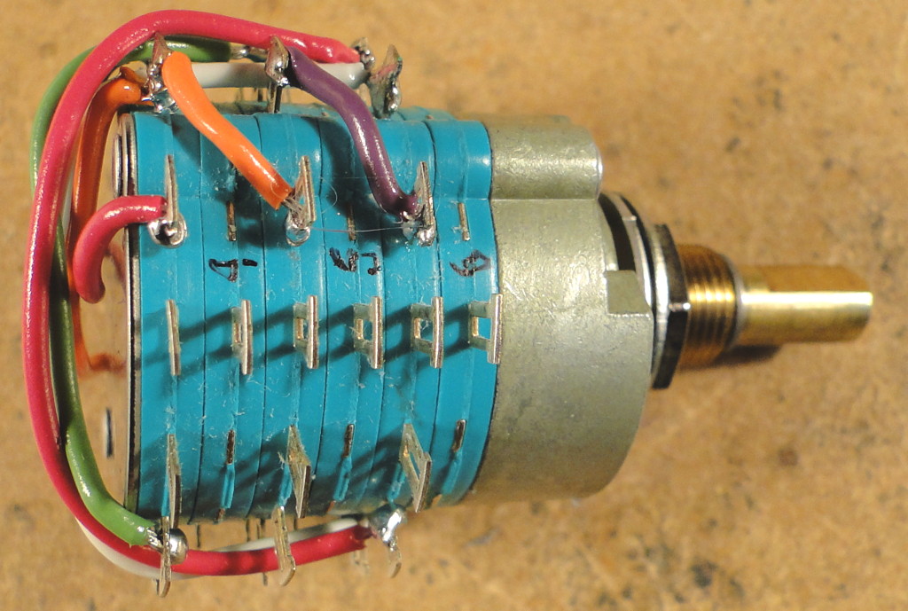
Rotary switch jumper detail (view #2). |
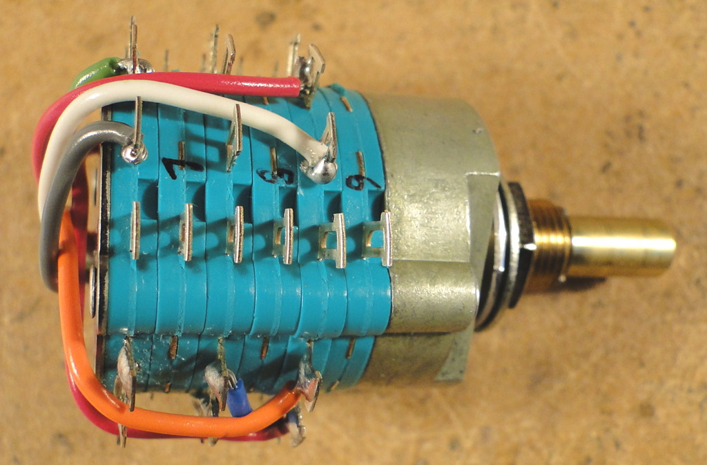
Rotary switch jumper detail (view #3). |
 |
 |
 |
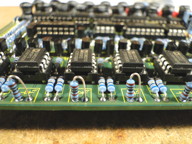 |
| Rotary switch detail. Add wires to input pots with inline 24K or 30K resistor (input position 1). |
Rotary switch detail. Add wires to VCA inputs (rotary switch outputs). |
Rotary switch detail. Add wires to delay line outputs (input positions 2, 3 and 4). |
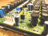
1K resistors in place of LEDs (when using separate LED drivers). |
 |
 |
 |
 |
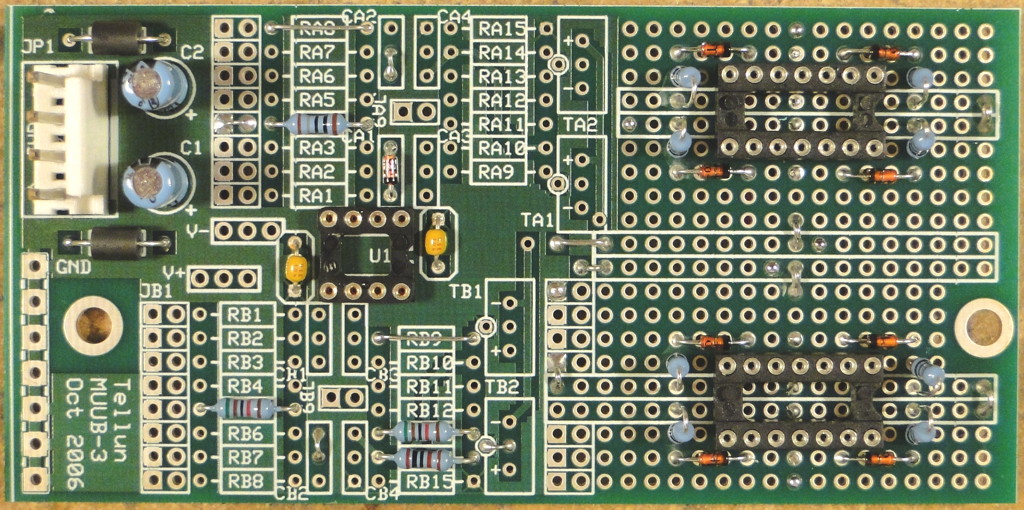
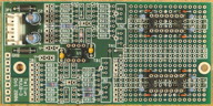
| LED driver detail. Top view of MUUB-3. |
LED driver detail. Top view of MUUB-3. |
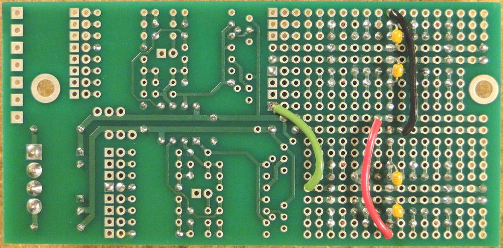
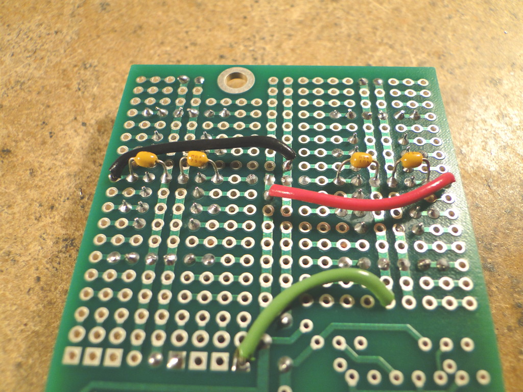
LED driver detail. Bottom view of MUUB-3. |
LED driver detail. Bottom view of MUUB-3. |
 |
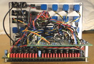 |
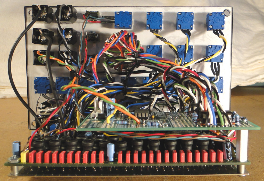
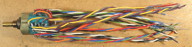
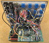
| Back view of finished module (lots of wires). |
Back view of finished module showing MUUB-3 mounted above PCB with 1" standoff. |