Back to All Mod Cons
Last updated: October 9, 2010
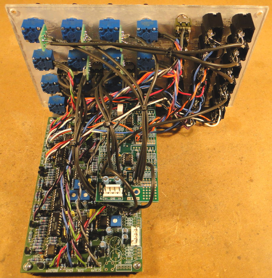
DescriptionBelow are details of my implementation of the JH Variable Slope Filter/Phaser into a 3U wide MOTM format panel. Be sure to check out Dave Brown's implementation as well because his build is very similar to mine plus he has a lot of additional information which you will find useful if you decide to build one of these. Grab the schematic and follow along with the explanations below. I built the additional circuitry onto a MUUB-4 and mounted it above the Varislope PCB using a single 1" threaded standoff. The MUUB is secure using just one screw but its position makes it a bit difficult to reach some of the trimmers on the Varislope PCB. I had to unscrew the MUUB and let it dangle in order to do the calibration. I'm using LM13700 chips (not LM13600) in this circuit. I don't know if this makes a difference or not. If you're using LM13600 chips, you might not get the same results from these modifications; you might have to change some of the resistor values. 1. Change Input Gain for 10Vpp SignalsChanged R1 from 51K to 100K and R2 from 300K to 100K to get unity gain through the filter with 10Vpp signals. With these values, 10Vpp at the input (IN) gives 10Vpp at the DRY output, and nearly 10Vpp at the FIL and INV outputs. 2. Add Three Input MixerReplaced the single pot at the input (R51) with a three input mixer. The 180K resistor in the feedback loop (R4 on my schematic) provides amplification at the input. This is in keeping with the levels on my MOTM filters which produce unity gain when the input level pots are somewhere between 7 and 8. I like to overdrive my filters and this allows me to do just that. 3. Change Output DriverReplaced the single transistor output buffer with an op-amp based mixer. Leave out R45, R46, R47, R48, C16, Q1, output attenuator R107 (reuse it for mixer), and the BYPASS switch. Note that 24K9 resistors are used for the DRY channel but 24K resistors are used for the FIL/INV channel in the mixer. This is just nit-picking to get an extra bit of gain from the FIL/INV channel which was just slightly less than 10Vpp through the filter. 4. Add Reversing Attenuator for FM1 InputAdded an inverter so that the FM1 input can be a reversing attenuator like on my MOTM filters. Also left out R59 because I'm not using the MOD3 input. 5. Add LED Driver for LFO OutputAdded a driver for a bicolour LED. This driver connects to R176 (where R176 connects to R175 and R177). I ran a jumper underneath the PCB from R176 over to the spot where R59 would go (I left out R59 because I'm not using the MOD3 input). This allowed me to use the MOD3 pad to run a wire from the Varislope PCB to the MUUB PCB where the LED driver is located. 6. Change AUX Input Gain for 10Vpp SignalsThe AUX input had way too much gain for my needs. Most of the levels in my synth are 10Vpp, not 1Vpp. Changed R127 from 10K to 44K2 to get unity gain with 10Vpp signals when the AUX level is set to the 12 o'clock position (midway). This still allows me to get a gain of 2X by turning the AUX input fully clockwise. |
||||||
Pictures
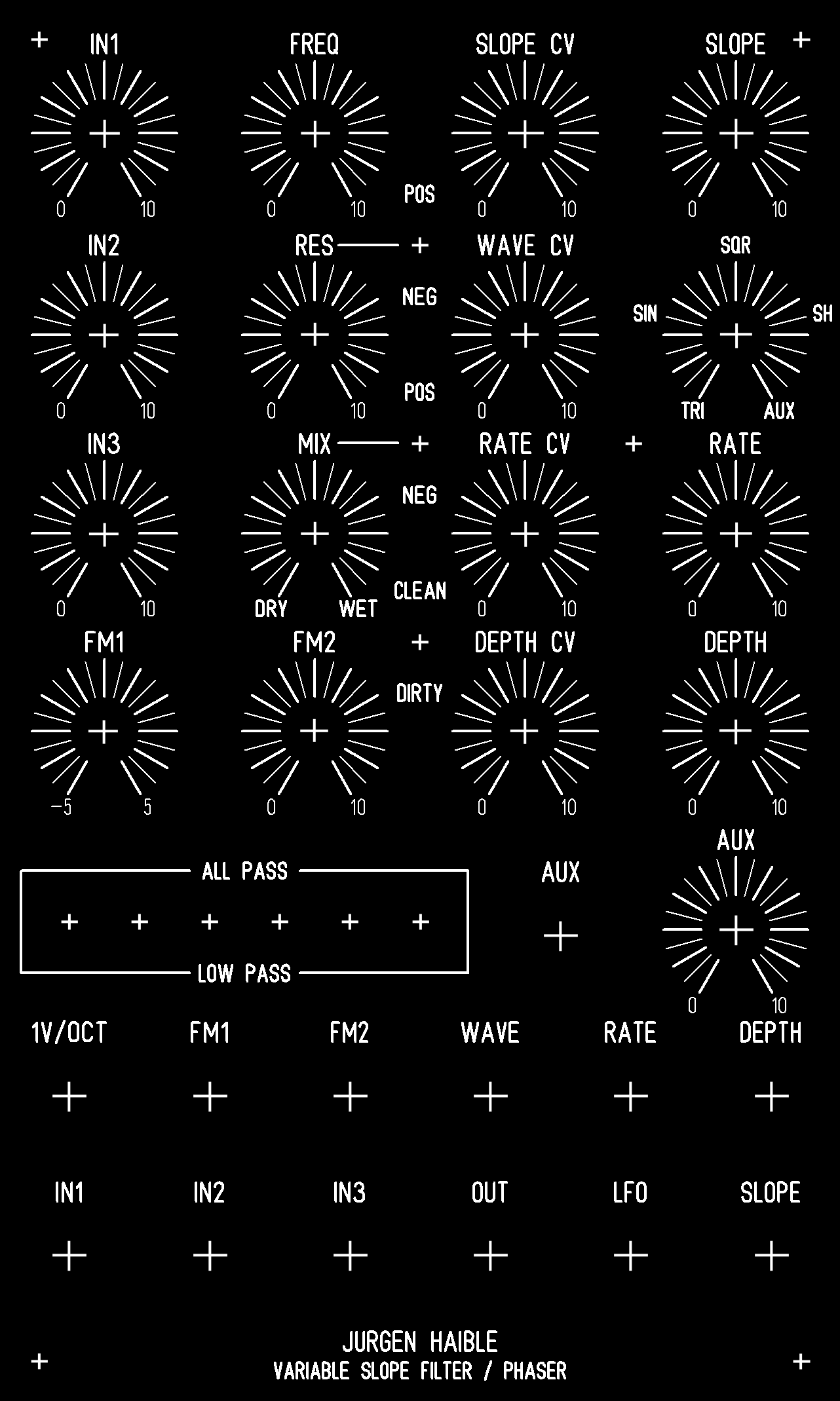
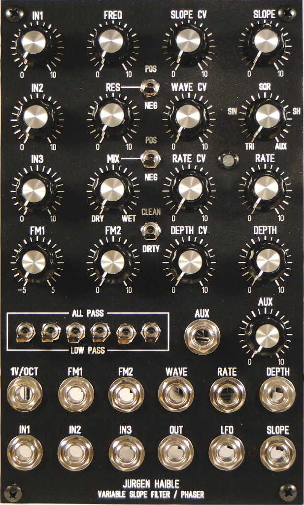
Panel LayoutI copied Dave Brown's FPD file and tweaked it to meet my needs. I bought a sheet of 1/8" plastic (clear lexan) at a hardware store and cut that into a number of panels (1U, 2U, 3U). I made an inverted printout of the panel in Front Panel Designer (black text on white background) and used that as a guide for drilling the holes in the plastic. I then printed out a screenshot of the FPD file using a laser printer and pasted it onto one of the plastic panels. In order to get smooth diagonal lines in the printout, I had to enlarge the panel (in Front Panel Designer) by 400% and then make multiple screenshots and stitch them together in a graphics program. Finally, I used an X-Acto knife to carefully remove the paper that covered the holes. The end result is not as sturdy as a metal panel, and doesn't provide any shielding, but it looks quite good and most people can't tell it's any different from the metal panels in my synth. |
||||||
Calibration NotesMake sure you have a copy of JH's calibration procedure and that you let the circuit warm up for a while before attempting to calibrate it. Note that I'm using LM13700 chips so you might get different results if you are using LM13600 chips. 1. Filter Cell Frequency AdjustmentSet all pots fully counter-clockwise. Don't plug anything into any of the jacks. Set all the filter switches to LOW PASS. Set the CLEAN/DIRTY switch to CLEAN. Set R62 (V/OCT trimmer) to the middle position. The MIX and RES switches are of no concern. Follow JH's instructions for setting the trimmers for the six filter cells. Start with 3, then do 1, 2, 4, 5, 6 in that order. Trimmer R84 (for cell #3) is particularly finicky, you will have a very tough time setting this to exactly -7.5V. Don't be too concerned with it because you will need to change it later on anyways. You will need to repeat the process for trimming the six filter cells several times because changing one trimmer seems to affect the response of the whole circuit (it took me four passes). In other words, after you trim cell 6, go back and trim cell 3 again, then do 1, 2, 4, 5, 6, then go back to 3 etc. Don't be too concerned about getting the exact voltages the first time through, anywhere from -7.4V to -7.6V is good enough for the first pass, you'll gradually hone in on the sweet spot with each pass. By the fourth pass you should be reading very close to -7.5V for each of the six filter cells. Once you've finished trimming the six filter cells, you'll then need to readjust R84 so that the FREQ pot is effective over its entire range. There is no right or wrong way to set this, you just need to set it to whatever works best for you. Ideally, you'll want the filter to cut off all frequencies when it's fully counter-clockwise and to pass all frequencies when it's fully clockwise. If you're building one Varislope, then you can probably just set R84 so that the filter cutoff matches your other filters as you rotate the FREQ pot. If you're building several Varislopes, you will likely want them to be matched to each other. Apply a 30 Hz sawtooth wave to the IN1 jack and turn the IN1 pot 75% clockwise. Turn the MIX pot fully clockwise. Keep all other pots fully counter-clockwise. Set all filter switches to LOW PASS. Set the CLEAN/DIRTY switch to CLEAN. Listen to the signal at the OUT jack (and hook it up to an oscilloscope if you have one). Turn R84 until the signal at the OUT jack completely disappears. Turn the FREQ pot clockwise, you should start to hear something (or see something on the scope) once the FREQ pot is greater than 10% clockwise. Verify that turning the FREQ pot fully clockwise opens up the filter all the way and that you can't hear any of the upper harmonics being removed from the sawtooth. When I had R84 set the way I liked it, I measured -14.00V (plus or minus a few mV) at each of the six filter cells when the FREQ pot was fully counter-clockwise. When the FREQ pot was fully clockwise, I measured +0.460V (plus or minus a few mV) at each of the filter cells. 2. Resonance AdjustmentThere's no right or wrong way to set the resonance trimmer R6. The following factors all affect this filter's self-oscillation: RES pot, RES switch, SLOPE, CLEAN/DIRTY switch, ALL PASS vs. LOW PASS switches. You'll just have to try out different settings to see what works best for you. In the end, I turned R6 fully clockwise (maximum resonance) since I can always use the RES pot to turn it down as required. 3. Sample & Hold AdjustmentHook up an oscilloscope to the LFO Output jack. Turn the RATE pot fully clockwise. Turn the WAVE pot to the S&H position (about 75% clockwise). Adjust R137 until the waveform reaches +/- 5V at it's maximum extent. Note that the S&H circuit takes a while to get going (mine takes at least 30 seconds to stabilize after initial power up), so don't try to set R137 immediately after turning on the power. 4. 1V/Octave AdjustmentTo set the 1V/OCT trimmer (R62) you'll need to have a voltage source that can output 1.00V to 4.00V in 1V increments and a reference oscillator. I used an MOTM-650 hooked up to a MIDI keyboard for the voltage source and a digital keyboard (outputing a sine wave) as the reference oscillator. Setup the voltage source and reference oscillator so that 1.00V corresponds to a frequency in the 100-150 Hz range and 4.00V corresponds to a frequency in the 800-1200 Hz range. Don't be too concerned about getting this filter to track accurately over a dozen octaves, three octaves in the mid range will be fine. I got mine to track quite well over 100 to 800 Hz and left it at that. This filter does not have temperature compensation, so the tracking will drift a bit: don't spend too much time on this. Connect the voltage source to the 1V/OCT input. Set all the filter switches to LOW PASS. Set the CLEAN/DIRTY switch to CLEAN. Set the RES switch to NEG. Set the MIX and RES pots fully clockwise. Set all other pots fully counter-clockwise. Listen to the filter output and turn the FREQ pot to make sure the filter can self-oscillate in the 100 - 1200 Hz range (or whatever range you are going to use with your reference oscillator). Set the voltage source to output 4.00V (or 3.00V), call this the "high note". The reference oscillator should be playing the "high note". Listen to the filter output and turn the FREQ pot until the filter output is in tune with the "high note" (no beating). Set the voltage source to output 1.00V, call this the "low note". The reference oscillator should be playing the "low note". Listen to the filter output and turn R62 until the filter output is in tune with the "low note" (no beating). Repeat the above two steps alternating between setting the "high note" and adjusting the FREQ pot with setting the "low note" and adjusting R62. After 5 or 6 passes you should get the filter to be in tune with both the high and low notes. Note that changing R62 will affect the filter's frequency response for all control voltage inputs, including the FREQ pot. Once you've got R62 set, check that the FREQ pot still works well over it's entire range. If not, adjust R84 (one last time) to suit. |