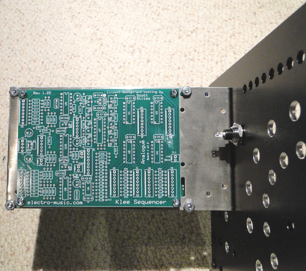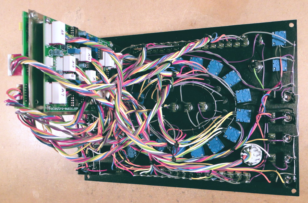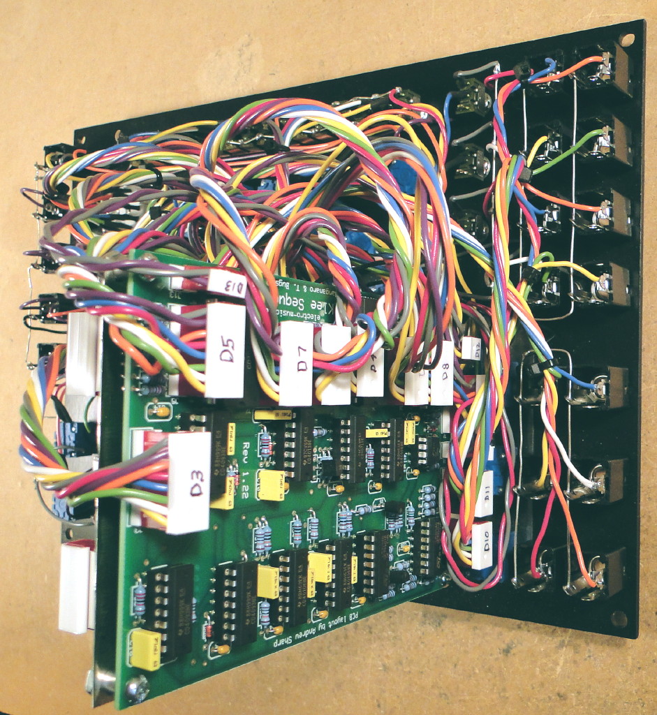
OverviewThis page details my implementation of Scott Stites' Model 2 Klee Sequencer. I used the electro-music.com PCBs and Bridechamber panel. I built this mostly "by the book" using MOTM-standard parts wherever possible. I also added one simple mod that allows cascading multiple Klees together (to create longer sequences). I used a Bridechamber 3-pot bracket for mounting the PCBs to the panel (one PCB on each side of the bracket). I had to drill a few extra holes in the bracket to get the PCBs to mount onto the bracket and to get the bracket to line up with the GLIDE pot holes on the panel (see the pictures below). I used BC549 transistors instead of 2N3904 transistors because I have lots of BC549s in my parts bin. You can substitute just about any NPN transistor because they are simply used as LED drivers. But before doing so, check the pinout of your transistor because (for example) the BC549 pinout is the mirror image of the 2N3904. So if you look at my completed PCBs you'll see that the transistors all appear to be mounted backwards (compared to the silkscreen) but they're not. I used MOTM-standard green Lumex LEDs for the gate outputs. For the clock and random input LEDs, I used a dremel to modify blue and orange LEDs so that they would fit into the MOTM-standard Lumex LED holder. I also changed the current limiting resistors for those LEDs so that they have a similar brightness to the rest of the LEDs in my synth. For the 16 pattern LEDs, I used the super-red version of the MOTM-standard Lumex LED because these LEDs are not driven by a transistor; they are driven directly from a CMOS chip which cannot supply very much current. I found that the regular red, green, and yellow MOTM-standard Lumex LEDs were not bright enough when driven directly from the CMOS chip and I didn't want to lower the current limiting resistors to compensate since this could be detrimental to the circuit. Luckily, the super-red LEDs are quite bright and they are available in the MOTM-standard format.
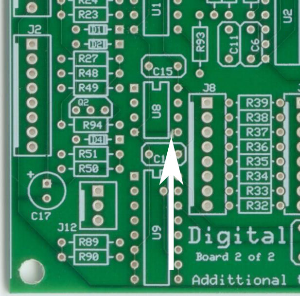
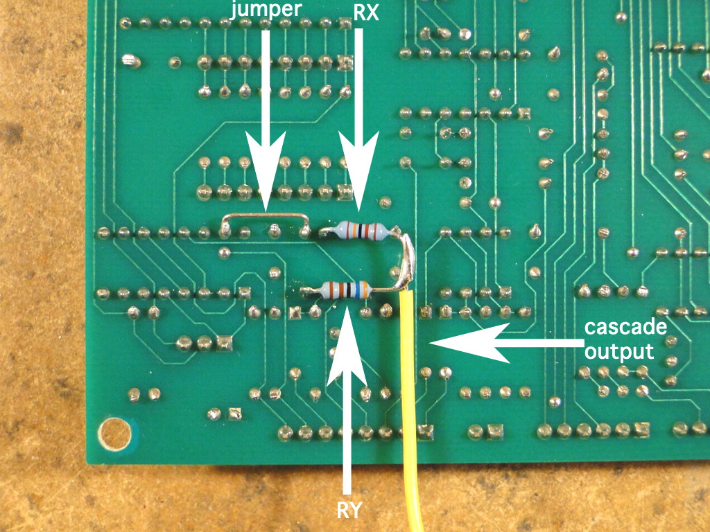
Cascade Output ModificationThe Bridechamber panel has a CLOCK THRU jack that is not part of the Klee circuit. My guess is that this jack is intended to pass the CLOCK IN signal to another module. I decided that I could make better use of this jack by using it to provide a shift register output signal that allows multiple Klees to be chained together to create longer sequences. Fortunately, the electro-music.com PCBs have some unused op-amps that make this quite easy to implement. To make this modification, you first need to cut a trace on the topside of the digital board to disconnect U8 pin 5 from ground (see the pictures below). Do this before soldering anything onto the digital board because the trace is underneath U8 which will be very difficult to do after you've soldered in a chip or socket. After you've soldered all the other components onto the digital board, use a spare resistor lead to jumper U9 pin 15 to U8 pin 5 on the underside of the digital board. Next step is to solder two resistors in series between U8 pin 6 and U8 pin 4 (ground). Use the same resistor values here that you used for the gate outputs: RX = whatever value you used for R63 through R70, RY = whatever value you used for R71 through R78. Finally, connect a wire at the junction of the two resistors and run this wire to the signal lug (tip lug) of the cascade output (CLOCK THRU) jack. Now that you've made this mod, how do you use it? The cascade output will be one of three signals (depending on how the Klee is configured):
These are the same three inputs that are fed to the shift register A input when the PATTERN/RANDOM switch is set to PATTERN. So if you have one Klee and you patch the cascade output to the RANDOM input and set the RANDOM level and threshold accordingly, the Klee will appear to be operating in PATTERN mode regardless of the PATTERN/RANDOM switch. Nothing fancy about that. But if you have two Klees and you patch the cascade output of Klee #1 to the RANDOM input of Klee #2 and patch the cascade output of Klee #2 to the RANDOM input of Klee #1, set the PATTERN/RANDOM switch on both Klees to RANDOM and set the RANDOM levels and thresholds accordingly, the two Klees will act as one 32 stage sequencer. Now start changing between 2x8 and 1x16 on the two Klees and that 32 stage sequencer is now 24 stages, or 16 stages. Add a third and fourth Klee into the picture and things start to get really interesting. 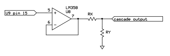
Construction Photos
|