Introduction
I've replaced the aging LCD display in my Korg Wavestation A/D. The new display is a Newhaven NHD-24064WG-ASMI-VZ# that I bought from Digikey (part number NHD-24064WG-ASMI-VZ#-ND). Mouser also carry some Newhaven displays and it appears that you can order them directly from Newhaven as well. The Newhaven display is slightly thicker than the original Optrex DMF5005N display, but I had no trouble fitting it to the Wavestation A/D. It's not quite "plug and play"; it does require a bit of soldering and three additional resistors, but the results are worth it. The Newhaven display is bright, has a lot of contrast, and since it uses a white LED for the backlight it completely eliminates that annoying high-pitched whine. The original Optrex display uses a CCFL backlight that is powered by an inverter circuit. The transformer in the inverter circuit creates that annoying whine. The Newhaven display does not need the inverter, so you can remove the transformer and stop the whining once and for all.
I got the idea to replace the display after seeing this.
The same upgrade being done on a Wavestation EX.
Procedure (grab the schematic and follow along):
- You can use the 20-pin ribbon cable that is connected to the original Optrex display (I used a new cable because I had one). Remove the ribbon cable where it connects to the Optrex unit by removing the top of the header then prying the ribbon cable off the 20-pin header. You can also cut the ribbon cable where it connects to the Optrex header, but try not to shorten the cable by too much.
- You'll need to extend the two wires that power the LED backlight on the Newhaven display if you intend to hook these up to the Wavestation motherboard. I clipped the two wires that connect to the CCFL backlight on the Optrex display and used those to extend the wires on the Newhaven display. This allowed me to use the 2-pin connector from the Optrex display to plug into the Wavestation motherboard to power the LED backlight on the Newhaven display (after removing the transformer for the inverter circuit and installing a 100 ohm resistor, more instructions on this below).
- Solder the 20-pin ribbon cable to the Newhaven display but don't solder pins 4, 9, 19, and 20.
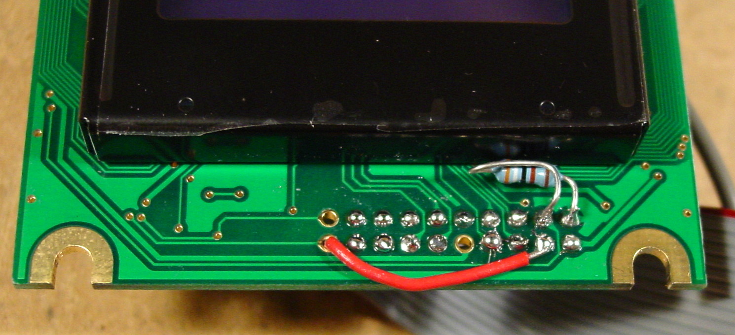
- Pin 19 on the Newhaven display needs to be pulled high (+5V) for the font selection. Run a short jumper between pins 19 and 3 on the Newhaven PCB (on the LCD side).
- Pins 9 and 20 on the Newhaven display are not connected to anything. You can clip these wires from the ribbon cable.
- The LCD contrast control (coming from the Wavestation motherboard) needs to be modified to work with the Newhaven display. The Newhaven display wants to have a voltage (on pin 4) of between -6V and -9V. If pin 4 is connected directly to the Wavestation, the voltage on pin 4 stays in the -10V range (which creates a white-washed display with no contrast control whatsoever). Install a 698 ohm resistor (in series) between pin 4 of the Newhaven display and pin 4 of the Wavestation. Use a piece of heat shrink tubing on this resistor to prevent it from coming into contact with the PCB. Also install a 3.9 Kohm resistor between pin 4 of the Newhaven display and pin 2 (ground) on the LCD side of the PCB. These two resistors create a voltage divider that will bring the voltage on pin 4 to the -6V to -9V range as the contrast control is varied on the Wavestation. You don't need to use these exact resistor values (others will work) but this is what I found to produce the best results.
- The two wires for the LED backlight on the Newhaven display need to be connected to +5V (red wire) and ground (white wire). You can connect these to pins 2 and 3 on the header, or run them back to the Wavestation motherboard and connect them there. You'll need to connect a current limiting resistor between +5V and the red wire on the Newhaven display. I found that a 100 ohm resistor produced a fairly bright display that only draws 20 mA of current. You can use a lower resistor value if you want a brighter display, but that will draw more current.
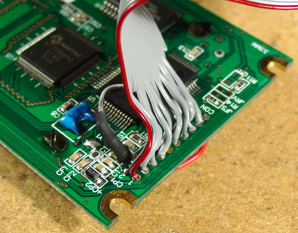
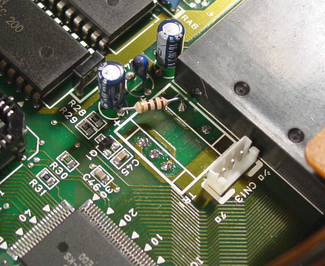
- Remove the transformer for the CCFL inverter circuit. This completely eliminates that annoying high-pitched whine and provides a good place to connect the 100 ohm resistor. One pin of the resistor connects to one of the pads where the transformer was connected (this pad connects to the 2-pin header). The other pin of the resistor connects to the + pin of a nearby electrolytic capacitor (this is +5V). You can then plug the 2-pin header onto the Wavestation's motherboard to power the LED backlight.
- Once you've got the Newhaven display wired up, test it out by plugging the 20-pin and 2-pin headers onto the Wavestation motherboard, then power up the Wavestation. Make sure the contrast control provides a good range of settings.
Pictures
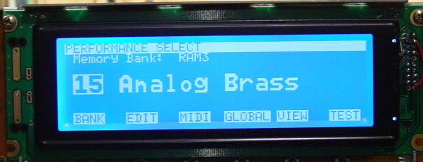
These pictures don't do justice to the new display. The new display has much higher contrast than these pictures show; the blue background is a medium sky blue and the text is bright white and sharply focused.
 |
 |
|
|
| Old display | New display | Transformer to remove (circled) | Transformer removed |
 |
 |
 |
 |
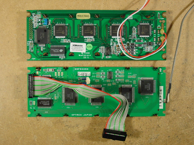
| New display (top) Old display (bottom) |
R1 in heat shrink | R2 and pin 19 jumper | R3 on motherboard |