Description
The TLN-712 Doomsday Machine is a voltage controlled waveform animator for modular synthesizers. Originally conceived as two separate modules, the TLN-712 comprises two different animation circuits and four voltage-controlled LFOs (low frequency oscillators). The first animator (Thalaran Radiation Emitter) is based on the Multi-Phase Waveform Animator by Bernie Hutchins. The second animator (Cascading Biogenic Pulse) is based on the Pulse Width Multiplier by Craig Anderton. Both animators have been combined into one module along with four LFOs to create a self contained system that makes optimal use of panel space. All you need to add is a single oscillator and a few patch cords to create a marvelous mayhem of sonic madness. Add a second oscillator and you'll never get a date to the prom.
Features:
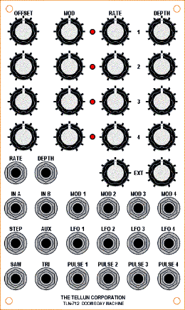
- Four modulation sources. Each source has an OFFSET pot to set the initial modulation point, a MOD input jack with attenuator to allow for external control of modulation, and an internal LFO. All four modulation sources are internally connected to both animators.
- Each internal LFO has a RATE pot, an LED to provide visual indication of the rate, and a DEPTH pot to set the amount of LFO fed to the animators. Each LFO has a 10 Vpp triangle wave output that is available for external use. Internally, each LFO provides a sine wave to the two animators.
- The rate and depth of all LFOs can be changed en masse using the EXT RATE and EXT DEPTH jacks and attenuators. Use these with a keyboard control voltage, mod wheel, or foot pedal to control both the speed and depth of animation.
- The Thalaran Radiation Emitter has one input jack (IN A) and three output jacks (SAW, TRI, STEP). A sawtooth wave is normally applied to IN A, but sine or triangle waves can also be used (almost any waveform except pulse waves will produce some kind of useful output). With a sawtooth input, the SAW output comprises the input signal plus four phase shifted versions of the input signal (sounds like five sawtooth waves). The phase shift is controlled by the four modulation sources. The TRI output provides a similar effect but with five triangle waves. The STEP output is a bizarre staircase waveform where the depth of each step is controlled by the four modulation sources.
- The Cascading Biogenic Pulse has two input jacks (IN B and AUX) and four output jacks (PULSE 1-4). A triangle wave is normally applied to IN B, but sine or sawtooth waves can also be used (almost any waveform except pulse waves will work). The four PULSE outputs produce an intense pulse width modulation (PWM) effect with single, double, triple, and quadruple pulses appearing at outputs 1-4 respectively. Think of it as PWM on steroids. The PWM effect is controlled by the four modulation sources. The AUX input can be used to provide an additional level of animation, or to cascade two TLN-712s to get even more intense PWM, or to provide a cross-product effect.
- All inputs and outputs are DC-coupled. Either animator can be used to produce strangely wonderful waveforms for modulating other signals. The Cascading Biogenic Pulse can even be used to generate rhythmic gates and triggers.

|
The Doomsday Machine can destroy life forms, ecosystems, and entire planets. Use at your own risk.
|
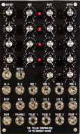
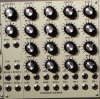
Note that the 3U wide panel layout for this module uses the smaller type of knob found on Encore Electronic's UEG and Frequency Shifter. Most people will probably hate this, but I wanted to get the most functionality in the least amount of space while still maintaining some semblance to the MOTM standard. Free free to design your own panel using standard MOTM size knobs and knob spacing. But be prepared to give up some of the features, otherwise you'll need a 5U wide panel to fit 20 jacks, 18 pots, and 4 LEDs. See the user guide for ideas on alternate panel designs.
Total current draw for TLN-712 is 150 mA @+15V and 150 mA @-15V. Requires 10 Vpp input waveforms for proper operation (e.g. MOTM-300 oscillator).
|
Downloads
The User Guide does not contain detailed explanations on how to install parts or which kinds of solder to use. The intended audience is the experienced kit builder who is quite comfortable building a circuit from a description, a parts list, and a schematic. Calibration routines are included.
|
Revision 1.0 (2007)
TLN-712 User Guide rev 1.0.1 (pdf)
TLN-712 Schematics rev 1.0 (pdf)
|
|
Revision 2.0 (2008)
Additional pads have been added for the four sine wave outputs so that these can be brought to front panel jacks. Four additional resistors have also been added to protect the op-amp outputs from being shorted to ground when a jack is inserted. These four outputs are not used on the 3U wide panel shown at left. However, they are used on the 5U wide Bridechamber panel.
TLN-712 User Guide rev 2.0 (pdf)
TLN-712 Schematics rev 2.0 (pdf)
|
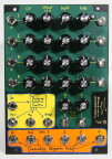
Detailed panel cutout diagram (pdf) with notes for those who want to build their own panel.
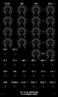
I copied an FPD file from Dave Brown and modified it for the TLN-712. I then printed out a screenshot of the FPD file using a laser printer and pasted it onto my plastic panel. It doesn't look too bad, especially in a dark room.
Click here to download the FPD file.
|
