JLH-2090CV Daughterboard for Blacet/Wizard Miniwave


Back to Synth DIY Projects

Last updated: December 17, 2005
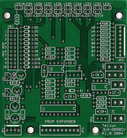
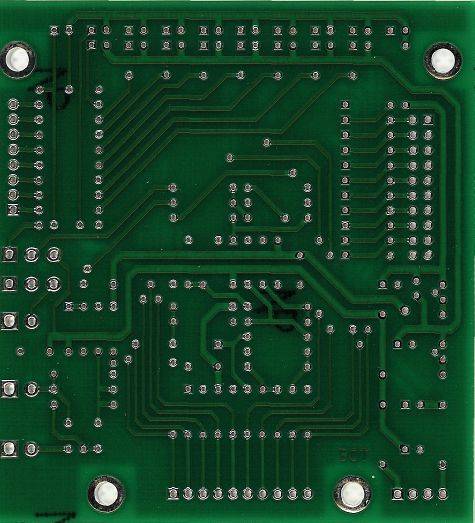
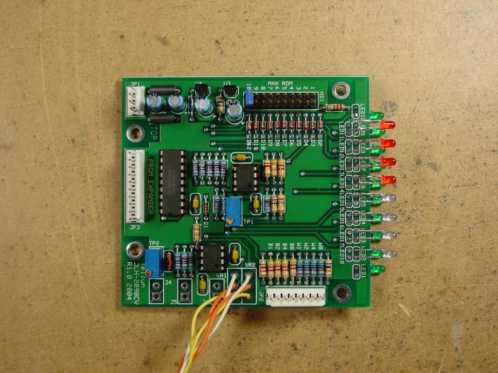
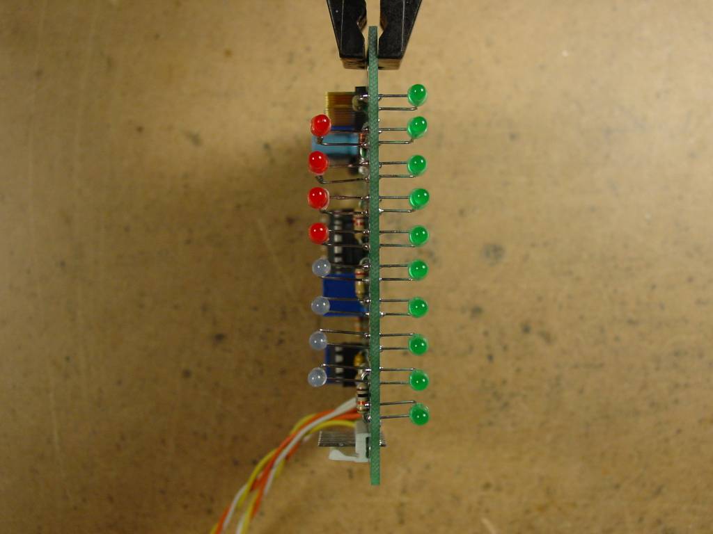
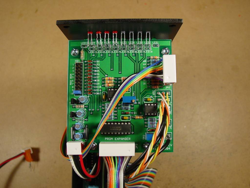
Description

The JLH-2090CV is a daughterboard for the Blacet/Wiard Miniwave. The JLH-2090CV is intended to be used with Dave Hylander's Miniwave ROM Expansion board. The JLH-2090CV adds voltage controlled switching of ROMs on the expansion board and an inverter for providing an inverted output from the Miniwave. The JLH-2090CV also provides space for mounting the Miniwave's four BANK and four WAVE LEDs.

Circuit design by Larry Hendry.

Availability

Sold Out

David Hylander is now handling distribution of the JLH-2090CV. Contact him if you are interesting in purchasing a PCB.

MOTM-style front panels for this module can be ordered from Stooge Panels.

Downloads

The User Guide is very light on construction details; it only contains a circuit description and parts list. See Larry Hendry's Miniwave pages for additional construction info.

JLH-2090CV User Guide rev 1.1 (pdf)

JLH-2090CV Schematics rev 1.0 (pdf)
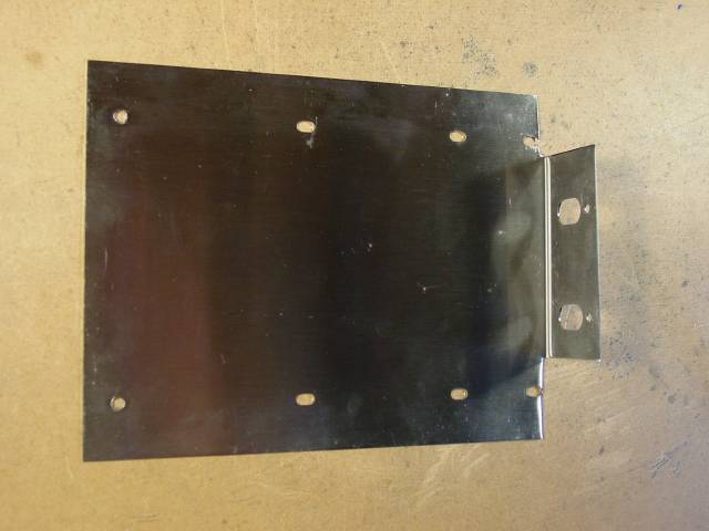
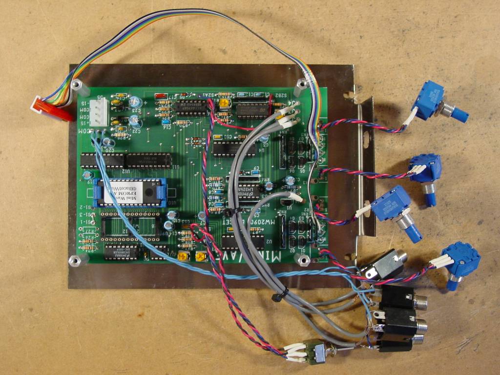
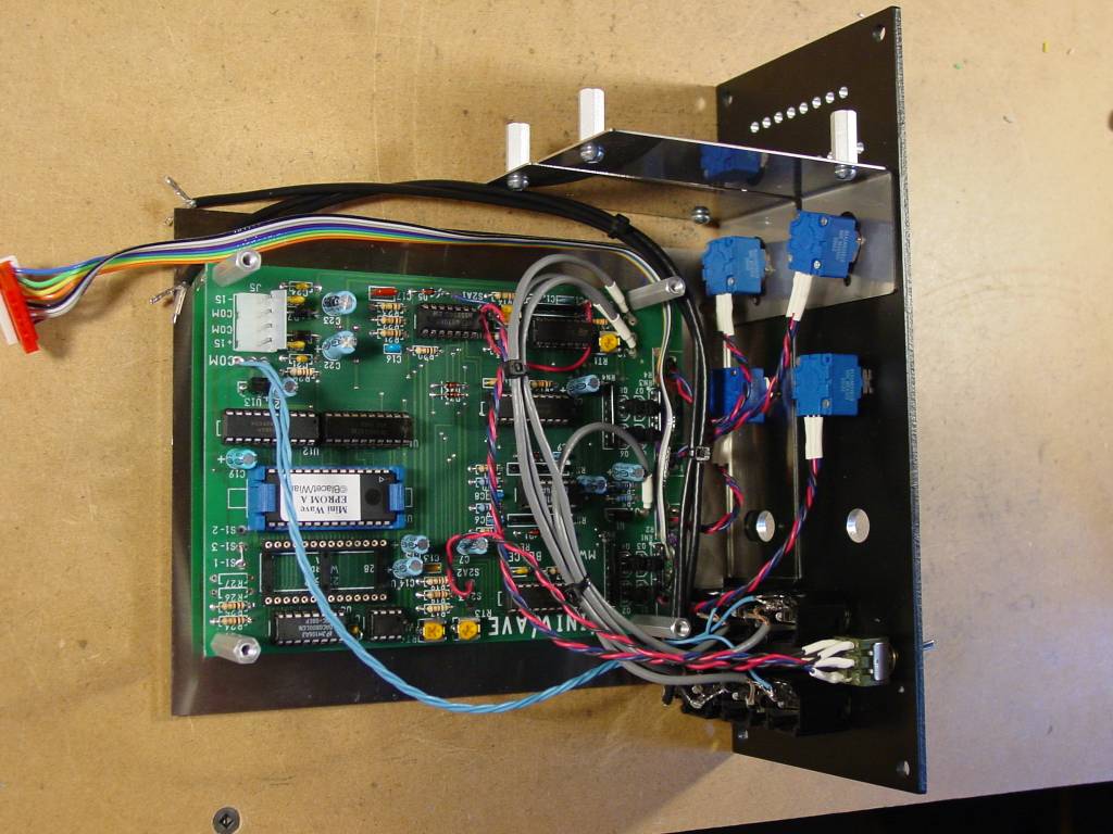
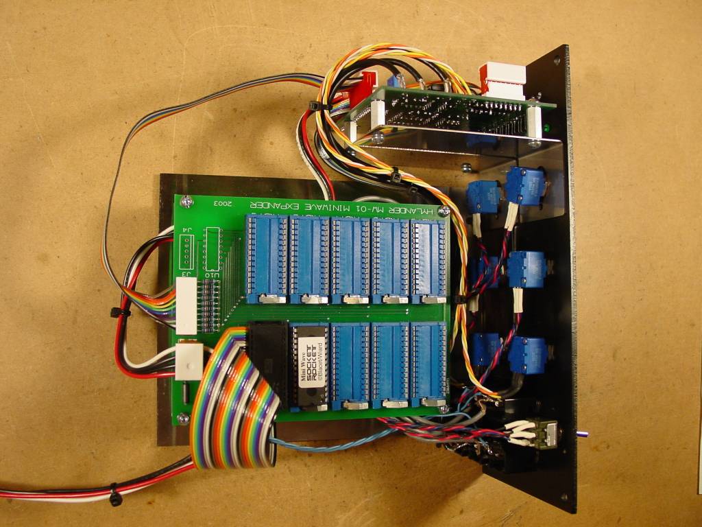
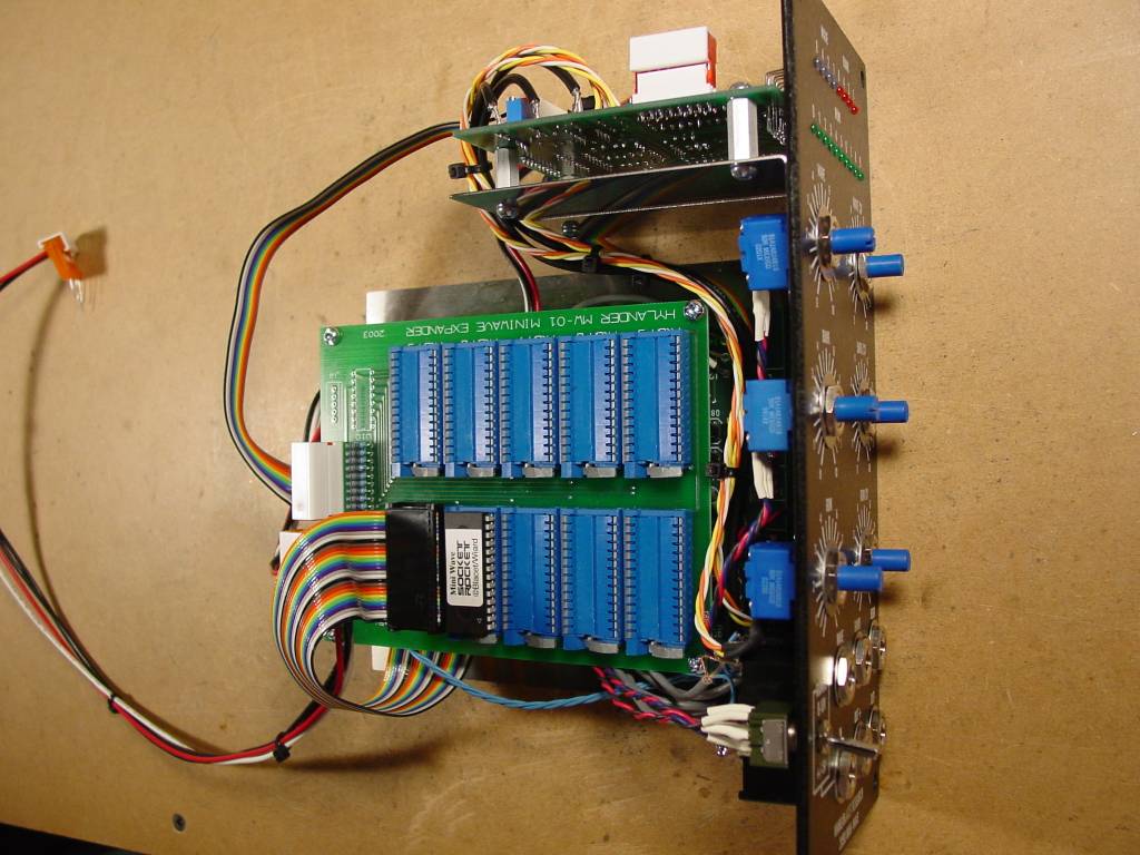
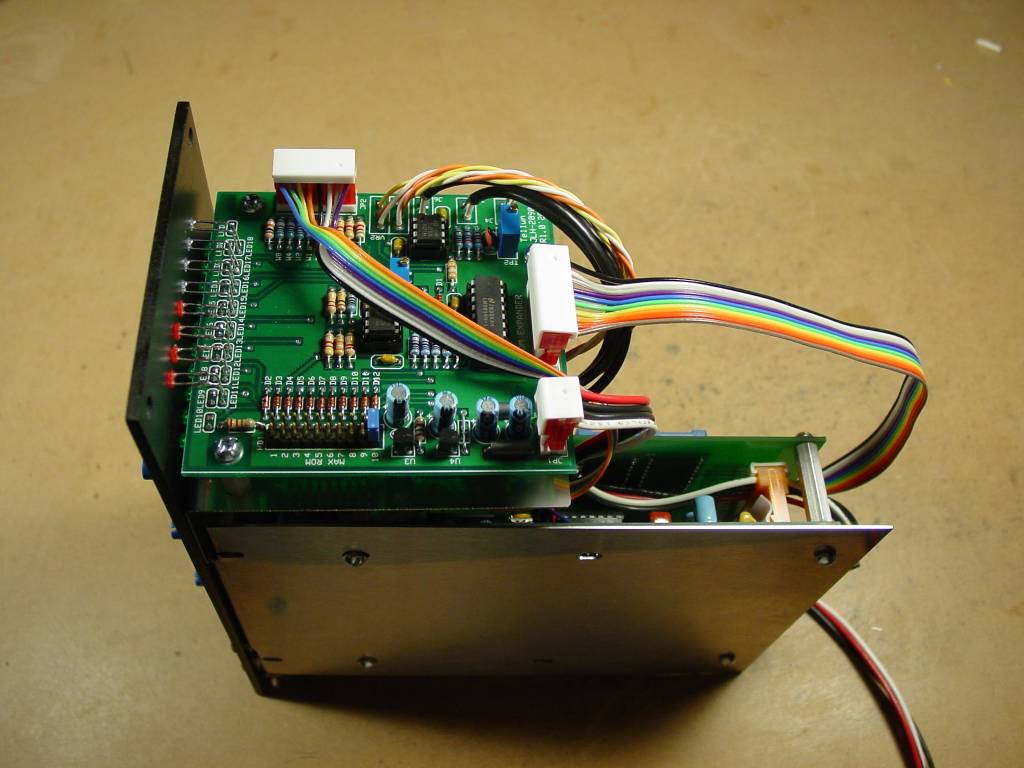
Construction Notes

I built my Miniwaves following Larry Hendry's example. I had previously built a couple of Miniwaves (with Stooge panels and brackets) that used the simpler A/B switch to select between two ROMs. Those brackets were trimmed so that only the two centre mounting holes remained. I had to get new panels to accomodate the JLH-2090CV but was able to reuse the brackets (see pictures below). Here are some notes I made:

  • I had to rotate the ROM CV jack so that the tabs faced downwards, otherwise the tabs interfered with the Miniwave motherboard. This was only an issue for my particular construction because I was reusing previously drilled Stooge brackets. Alternatively, I could have moved the Miniwave motherboard further away from the ROM CV jack by drilling new holes on the Stooge bracket.
  • Make sure to leave enough space for the MTA-100 connectors on top of the JLH-2090CV. Don't position the JLH-2090CV too high otherwise the tops of the MTA-100 connectors can interfere with the 1/2 inch space normally reserved for mounting the module in a wood cabinet. I positioned the JLH-2090CV directly in the middle of the two LED rows and it just fits. You can always remove the plastic caps from the connectors if things get too tight.
  • Make sure you get LEDs with leads long enough to reach the JLH-2090CV. I reused the LEDs from my previous Miniwave and some of them had been trimmed too short. Luckily, it was easy enough to extend the LED leads using scrap wires cut from the other components.
  • Most of the wires connecting the JLH-2090CV to the other PCBs and pots/jacks are 12 inches long. The 10 wire connector to Dave Hylander's expander board is 9 inches long.
  • Ribbon cable doesn't always make good contact with the MTA-100 connectors. I had to solder some of the wires to the MTA-100 headers to ensure a consistent connection. You can get MTA-100 connectors that will work better with thinner wires, I didn't have any on hand.
  • Use two MTA-156 pass thru connectors for supplying power to the Miniwave motherboard and Dave Hylander's expander board. This allows using one power cable to reach all three circuit boards. Note that I'm using the original version of the expander board. Newer versions may have different connectors.

Pictures

JLH-2090CV_pcb_tops.jpg JLH-2090CV_pcb_bots.jpg JLH-2090CV_pcb_bots.jpg
PCB Top View PCB Bottom View Stooge Panel
JLH-2090CV_brackets.jpg JLH-2090CV_mbs.jpg JLH-2090CV_mbends.jpg
Trimmed Bracket Board Stuffed LED End View
JLH-2090CV_process1s.jpg JLH-2090CV_process2s.jpg JLH-2090CV_process3s.jpg
Main Board Stuffed Main Board Attached LED Board Attached
JLH-2090CV_process4s.jpg JLH-2090CV_process5s.jpg JLH-2090CV_process6s.jpg
Finished Finished Finished
JLH-2090CV_process7s.jpg
Finished